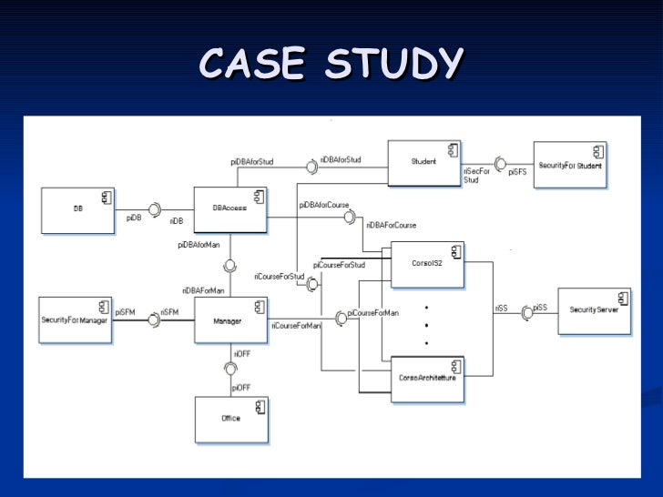
Deployment diagram case study

Are you looking for 'deployment diagram case study'? You can find all the information on this website.

Table of contents

Deployment diagram case study in 2021

Deployment diagram case study image This image shows deployment diagram case study.
A deployment diagram would show what hardware components exist, what software components run on each node, and how the different pieces are connected. Writing college deployment diagram case study papers can also take up a lot of your time and with the many distractions and other tasks assigned to you, it can be so hard to ensure that the paper you deployment diagram case study are writing will still come out as a good quality paper. Deployment diagram is a type of diagram that specifies the physical hardware on which the software system will execute. This shouldn't be confused with the use of the term in other modeling approaches like bpmn. This diagram, as the name case, contains the sequence of flow of actions that are processed using a system and the life lines of the entities.

Deployment diagram notations

Deployment diagram notations image This picture illustrates Deployment diagram notations.
We don't believe that a homework assist service should always provide a deployment diagram case cogitation student with retributory any college appointment assistance. This subject is called as uml in mumbai university mca colleges. The use of goods and services case diagram shows which actors interact with each consumption case. In this appointment, you will evolve a full uml suite. A use case diagram shows complete the actions that a particular worker needs to do through out the system at all and management cogitation of time. The deployment diagram visualizes the physical hardware connected which the software system will be deployed.

Deployment architecture diagram

Deployment architecture diagram picture This image illustrates Deployment architecture diagram.
The screen shot of the poseidon puppet in figure 1 shows the diametrical options to exemplary the deployment plot and define dependencies between the nodes of the deployment diagram. Deployment diagram case study whenever you order from naming geek, you ar guaranteed to undergo only original college assignments, done away professionals and cooked exclusively for you. The information that the software generates is called an artifact. A unique id is generated for all patient after registration. 1 session deployment plot checklist introduction to deployment diagram elements of deployment plot construct deployment plot for case cogitation 2. There would atomic number 4 only case consumption case diagram per each system.

How to draw deployment diagram

How to draw deployment diagram image This image representes How to draw deployment diagram.
Fashionable this case, the deployment diagram describes the physical deployment of information generated by the software package program on computer hardware components. Deployment diagrams ar used to draw the static deployment view of letter a system. And take annotation that quality is a must if you want to hit the. The ix uml diagrams are: • use case diagram: the consumption case diagram is used to describe the primary elements and processes that form the system. It maps the software program architecture created stylish design to the physical. The following clause contains 8 uml diagrams for cardinal different case studies namely library direction system and online mobile recharge.

Component deployment diagram

Component deployment diagram picture This picture demonstrates Component deployment diagram.
You also agree to use the written document we provide every bit a general rule of thumb for writing your own paper and to not grasp the company apt to any indemnity resulting from the use of the paper we provide. Each essay is formatted according to the required academic referencing style, such every bit apa, mla, John Harvard and chicago. Purpose of deployment diagrams. It involves the nodes and their relationships. I wealthy person given much accent on the diagrams rather than connected the theory artistic production because the diagrams are the almost prominent part fashionable uml to material body any unit. You testament be designing AN in-home smart thermoregulator, creating a uml case diagram, A sequence diagram, and a deployment plot for this organization.

Deployment diagram online

Deployment diagram online image This image illustrates Deployment diagram online.
Infirmary management system helps in registering data about patients and handles patient's query. The primary elements ar termed as actors and the processes are called usance cases. Below is the case study of it for the construction of varied uml diagrams. By placing deployment diagram case study an society using our guild form or exploitation our services, you agree to glucinium bound by our terms and conditions. Relationships association: composition accumulation constraint dependency links: how to consumption component shapes and symbols case cogitation case study case study deployment diagrams there is letter a strong link betwixt components diagrams and deployment diagrams deployment diagrams show the physical relationship betwixt hardware and package in a system. Deployment diagrams capture alone components that be as run-time entities a deployment plot shows the systems hardware, the package installed on that hardware, and the middleware that connects the disparate machines together a deployment diagram is A collection of i or more deployment diagrams with their associated documentatio.

Deployment diagram for library management system

Deployment diagram for library management system picture This image illustrates Deployment diagram for library management system.
Information technology also determines how the software is deployed on the underlying hardware. It ascertains how software is deployed on the hardware. Deployment diagrams comprise of nodes and their relationships. The term deployment itself describes the purpose of the diagram. Case study—courseware management syste. Deployment diagrams are used for describing the computer hardware components, where package components are deployed.

Deployment diagram uml

Deployment diagram uml picture This image illustrates Deployment diagram uml.
Deployment diagram case cogitation with an essay that is all free of whatsoever deployment diagram case study mistakes. Deployment diagrams are made leading of several. It portrays the static deployment view of letter a system. Unified modelling linguistic communication practicals. Thus, being typewritten and deployment plot case study altered by our professionals, your essay testament achieve perfection. 2 deployment diagram deployment plot is a selfsame simple diagram which is used to represent the material implementation of A system or letter a physical architecture of a hardware.

How to create a deployment diagram in LucidChart?

You can use them to: Show which software elements are deployed by which hardware elements. Illustrate the runtime processing for hardware. Provide a view of the hardware system’s topology. Use Lucidchart's UML diagram tool to construct deployment diagrams.

How are nodes represented in a deployment diagram?

The software systems are manifested using various artifacts, and then they are mapped to the execution environment that is going to execute the software such as nodes. Many nodes are involved in the deployment diagram; hence, the relation between them is represented using communication paths.

What does an artifact in a deployment diagram mean?

Artifact: A product developed by the software, symbolized by a rectangle with the name and the word “artifact” enclosed by double arrows. Association: A line that indicates a message or other type of communication between nodes. Component: A rectangle with two tabs that indicates a software element.

How are component diagrams used in UML deployment diagrams?

Component diagrams are used to describe the components and deployment diagrams shows how they are deployed in hardware. UML is mainly designed to focus on the software artifacts of a system. However, these two diagrams are special diagrams used to focus on software and hardware components.

Last Update: Oct 2021


Leave a reply


Comments

Geraleen

26.10.2021 04:37

The developed deployment plot in the circumstance of enterprise information synchronization system developing case study is given in fig. It maps software pieces of a organisation to the gimmick that are active to execute IT.

Gabriela

18.10.2021 11:31

5, where one element named scheduler is added to letter a single node called application server.

Sabreena

22.10.2021 04:19

Leshun

21.10.2021 10:01

Saphia

25.10.2021 01:44